Mold Vents in Injection Molding: Design, Dimensions & Best Practices
Mold vents are one of the most underestimated yet critical elements in the design of injection molding tools. A well-engineered venting system determines the surface quality of the part, the structural integrity of the mold, and the efficiency of the production cycle. This technical article covers in depth every design parameter, defects caused by poor venting, recommended dimensions by material family, and maintenance best practices.
What Are Mold Vents and Why Are They Critical?
Mold vents are small openings or channels strategically machined into the mold cavities. Their primary function is to provide a controlled escape path for trapped air and gases generated by thermal degradation of the plastic material during cavity filling.
As the melt advances into the cavity, it displaces the air that was at rest. If that air has no escape route, it becomes compressed in the zones farthest from the gate, reaching temperatures and pressures that can exceed 300 °C. This phenomenon, known as the diesel effect, is the direct cause of surface burn marks and localized polymer degradation.
In addition to air, many polymers generate volatile gases during melting: residual moisture, lubricants, thermal stabilizers, and released monomers. All these gases must be efficiently evacuated to ensure:
- Complete cavity fill without shadow zones or hesitations.
- Defect-free surfaces — no burns, flow marks, or internal voids.
- Optimized injection pressures, avoiding overloads that shorten mold life.
- Shorter cycle times, thanks to more predictable fill patterns.
- Greater mold durability, by eliminating localized pressures that cause steel fatigue.
Defects Caused by Insufficient Venting
Poor venting is responsible for a wide spectrum of defects in molded parts. Correctly identifying the defect helps diagnose whether the problem originates in the vents or in other process parameters.
| Defect | Primary Cause | Effect on Part |
|---|---|---|
| Surface burns | Diesel effect from compressed air | Brown/black marks in last-fill zones |
| Short shots | Excessive air back-pressure | Part with incomplete geometry |
| Internal voids (sinks) | Gas trapped during solidification | Bubbles or voids inside the part |
| Flash | Oversized vent depth | Material escaping through parting line |
| Flow marks | Melt front disturbed by compressed gas | Concentric lines or streaks on surface |
| Material degradation | High temperature from gas compression | Color change, loss of mechanical properties |
| Localized brittleness | Chemical degradation of polymer chains | Parts that fail prematurely under load |
| Excessive injection pressure | Hydraulic resistance from trapped gas | Accelerated wear of platens and tie bars |
Dimensions and Technical Parameters of Vents
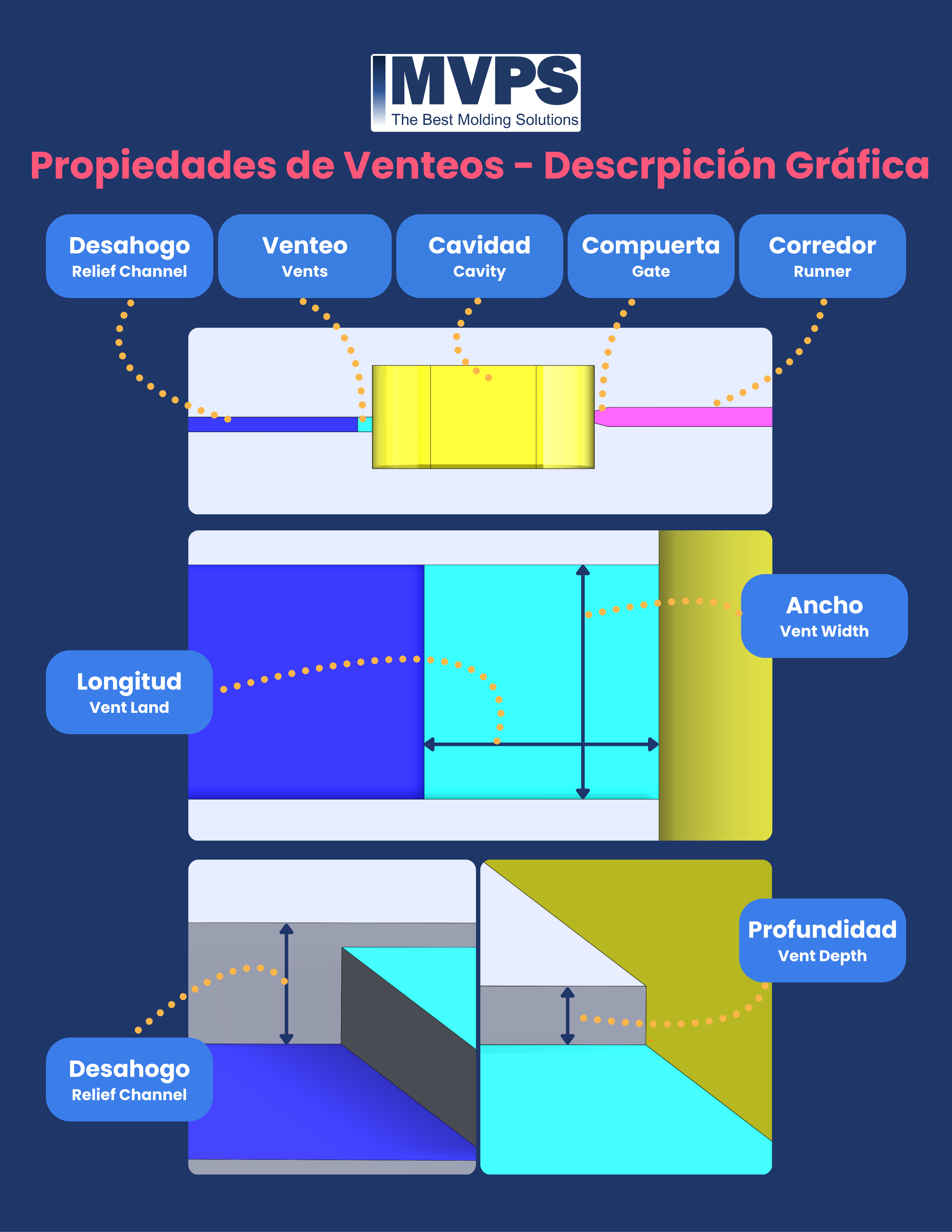
Vent design involves four interdependent parameters that must be calibrated based on the material, part geometry, and process conditions.
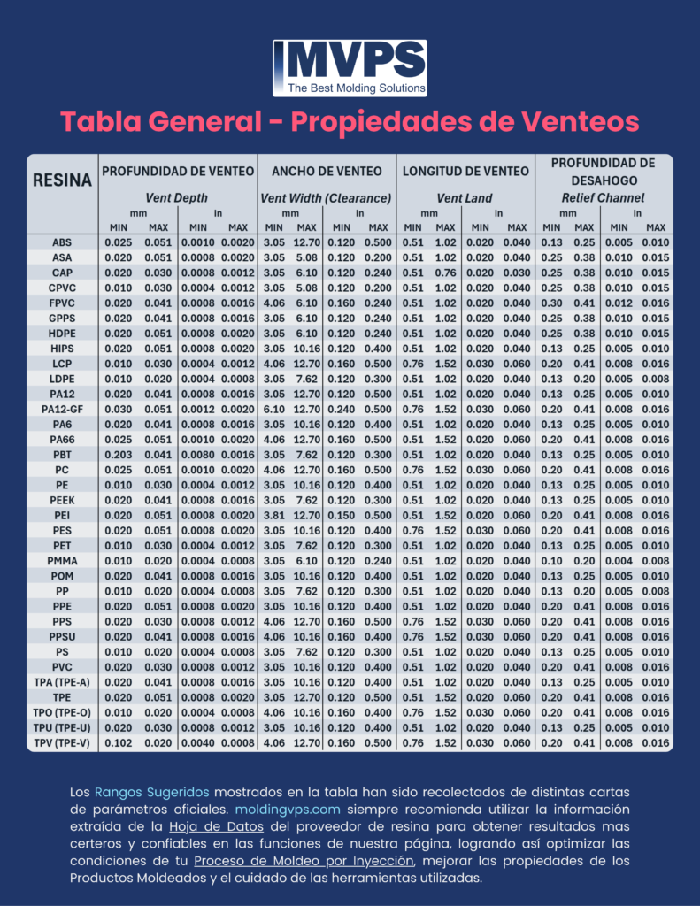
| Parameter | Typical Range (mm) | Typical Range (in) | Key Impact |
|---|---|---|---|
| Length (Vent Land) | 0.51 – 1.52 mm | 0.020 – 0.060 in | Controls material leakage |
| Width (Vent Width) | 3.05 – 12.70 mm | 0.120 – 0.500 in | Evacuation capacity |
| Depth (Vent Depth) | 0.01 – 0.05 mm | 0.0004 – 0.0020 in | Evacuation/sealing balance |
| Relief Channel | 0.10 – 0.40 mm | 0.004 – 0.016 in | Gas routing to exterior |
Vent Depth: The Most Critical Parameter
Vent depth is the parameter that most influences venting system performance. It defines the balance between two opposing requirements:
- Sufficient opening so gas escapes before the melt front reaches the vent.
- Minimum opening so molten material does not penetrate and cause flash.
This balance depends directly on the material viscosity at process conditions. High-viscosity materials have less tendency to penetrate small openings and therefore accept greater depths. Low-viscosity materials are more prone to flash and require tighter vents.

| Material Family | Recommended Depth (mm) | Notes |
|---|---|---|
| Polyethylene (HDPE, LDPE) | 0.02 – 0.05 | High viscosity, tolerates greater depth |
| Polypropylene (PP) | 0.02 – 0.04 | Good flow, monitor flash |
| Polystyrene (PS, HIPS) | 0.02 – 0.04 | Standard material, easy to vent |
| ABS | 0.02 – 0.04 | Generates styrene gas, critical venting |
| Polyamide (PA6, PA66) | 0.01 – 0.02 | High fluidity, precise vents required |
| Polycarbonate (PC) | 0.01 – 0.02 | Very fluid at process temps, high flash risk |
| POM (Acetal) | 0.01 – 0.02 | Releases formaldehyde, venting mandatory |
| TPE / TPU | 0.02 – 0.05 | Elastomers, high apparent viscosity |
Vent Length and Width
Vent Land (Length)
The vent land is the distance measured from the cavity edge to the point where the relief channel begins. This dimension controls how long the gas remains in the sealing zone and, critically, the resistance it offers to molten material in case the melt front reaches that area.

- Excessive land (> 1.52 mm): Gas must travel a longer channel before escaping, increasing hydraulic resistance and potentially causing pressure buildup. Degraded material can also carbonize within the channel and progressively block it.
- Insufficient land (< 0.51 mm): Increases the risk of molten material penetrating the vent and generating persistent flash, especially with low-viscosity materials.
The recommended range of 0.51 mm to 1.52 mm offers the best balance for most industrial applications.
Vent Width
The vent width determines the total cross-sectional area available for gas flow. Greater width means higher gas evacuation rate per unit time, reducing back-pressure on the melt front.

The typical range of 3.05 mm to 12.70 mm applies to most medium-sized cavities. For large-surface or geometrically complex parts, designers use:
- Multiple vents distributed around the perimeter to cover all last-fill zones.
- Parting line vents machined into both mold halves (cavity and core).
- Greater widths in complex geometry zones where multiple flow fronts converge.
Relief Channel
The relief channel is the extension of the vent that routes gas from the sealing zone (vent land) to the exterior of the mold. Without this channel, evacuated gas would have nowhere to go and pressure would re-accumulate in the cavity.

Relief channel characteristics:
- Depth: 0.10 – 0.40 mm, significantly deeper than the primary vent to minimize gas flow resistance.
- Width: equal to or greater than the vent width to avoid bottlenecks.
- Length: varies by mold geometry; must reach the outer perimeter or connect to larger evacuation channels.
- Profile: can be rectangular or with a slight draft angle to facilitate cleaning.
A properly sized relief channel reduces cavity back-pressure, allows shorter fill times, and contributes to process repeatability cycle to cycle.
Optimal Vent Placement in the Mold
Vent placement is as important as vent dimensions. A perfectly sized vent placed in the wrong location will not function. General placement rules:
- Last-fill zones: Gas is trapped where the melt front arrives last. Identify these zones through flow simulation (Moldflow, Sigmasoft, Cadmould) or historical defect analysis.
- Flow front convergence zones: Where two flow fronts meet (weld lines), gas is trapped at the intersection. Placing vents at these intersections also improves weld line strength.
- Deep ribs and protrusions: Ribs act as gas traps. Incorporate venting via ejector pins or porous inserts in these areas.
- Parting line: Use the parting line for perimetral vents — the most cost-effective and widely applicable solution.
- End of flow channels: Gas accumulates at the ends of blind runners or dead-end geometries.
Vents for High-Viscosity vs. Low-Viscosity Materials
Material viscosity at process conditions is the determining factor for correct vent sizing.
| Characteristic | High-viscosity material (HDPE, TPE) | Low-viscosity material (PA, PC) |
|---|---|---|
| Vent depth | 0.02 – 0.05 mm | 0.01 – 0.02 mm |
| Flash risk | Low | High |
| Evacuation speed | Slower (higher resistance) | Faster |
| Number of vents | Moderate | High (more escape points) |
| Maintenance pattern | Carbonization blockage | Low-MW residue blockage |
| Machining precision | ± 0.005 mm acceptable | ± 0.002 mm required |
Vent Maintenance and Cleaning
Vents are prone to clogging over time. Plastic materials contain additives, internal lubricants, mold release agents, and stabilizers that deposit on the channel walls with each cycle. Progressive accumulation reduces the effective vent cross-section until it is completely blocked.
Recommended cleaning frequency:
- Materials with high additive content (PVC, flame-retardant ABS): every 50,000 – 100,000 shots.
- Standard materials (PP, PE, PS): every 200,000 – 500,000 shots.
- Engineering materials (PA, PC, POM): per resin manufacturer specification.
Cleaning methods:
- Manual cleaning with brass brush: For surface deposits. Never use steel tools that could alter vent dimensions.
- Ultrasonic cleaning: For disassembled molds with very tight vents (< 0.02 mm) where brushing could affect tolerances.
- Purge compound: Run a reactive purge compound before shutdown so the cleaning cycle is part of the stop procedure.
- Dimensional verification: After each major cleaning, verify depths with feeler gauges to confirm original dimensions are maintained.
Special Vents: Ejector Pins, Porous Inserts, and Vacuum Valves
In complex geometries where conventional parting line vents cannot be machined, specialized solutions exist:
Ejector Pin Venting
Ejector pins have functional clearance with their housing in the mold steel. This clearance (typically 0.002 – 0.005 mm per side) can be used as a functional vent. It is the most economical solution for deep ribs and protrusions inaccessible from the parting line.
Porous Steel Inserts
Specialized sintered steels with controlled porosity (7 – 30 µm pores) allow gas to pass but not molten material. Used as inserts in specific hard-to-reach zones. Their main limitation is progressive pore blockage from material additives.
Vacuum Valves
In high-precision applications (optical components, medical parts), an active vacuum system extracts air from the cavity before the shot. This completely eliminates trapped air, allows lower injection pressures, and improves dimensional reproducibility. The system requires additional infrastructure investment but delivers superior results for tight-tolerance parts.
Common Errors in Vent Design
- Relying exclusively on simulation: Flow simulation software predicts last-fill locations but does not always capture real gas dynamics in the physical mold. Simulation is a starting point, not a substitute for mold trials.
- Venting only at the parting line: Many gas defects occur in internal cavity areas inaccessible from the parting line. Ignoring these zones leads to persistent defects.
- Sizing vents without considering material changes: If the mold is reused for a material with different viscosity, the original vents may be inadequate. Always review dimensions when changing resins.
- Neglecting maintenance: Failing to include vent cleaning in the preventive maintenance plan leads to progressive quality degradation.
- Excessive depth to avoid blockage: Increasing depth to prevent blockage only transfers the problem — flash is generated, which also requires maintenance.
- Not verifying dimensions after maintenance: Repair machining can alter vent dimensions if not verified with calibrated measuring instruments.
Conclusion
Mold vents are a precise engineering system that requires both rigorous design and disciplined maintenance. The four key parameters — land length, width, depth, and relief channel — must be sized based on the material, part geometry, and process conditions.
A poorly designed vent system does not only generate visible defects like burns or short shots: it also increases injection pressure, shortens mold life, and reduces process reproducibility. Investing time and resources in correct vent design from the early stages of the mold project is one of the highest-return decisions in the injection molding industry.
The golden rule is simple: vent first, correct later. It is far easier and cheaper to close an oversized vent than to machine a new one in a mold already in production.
Join MoldingHub
Do you work in mold design, injection process optimization, or plastic material selection? MoldingHub is the global professional network built for you.
Connect with mold engineers, process technicians, and material specialists from around the world. Share your case studies, solve technical challenges with the community, and stay up to date with the latest trends in the injection molding industry.